Adoption of Air-Supported Forms for Thin-Shell Concrete Structures: Understanding Uses, Benefits, and Barriers to Scale

Figure 1: Pantheon—Rome, Italy (world’s largest unreinforced cementitious dome 43.4m diameter, 1.4–5.9m shell thickness)
Abstract
Air-supported fabric forms for the construction of thin-shell concrete structures are a demonstrated option for efficiently scaling thin-shell structural geometries in the built environment. With an almost 100-year history of development, it is estimated that the air-supported forming processes has been used to construct over 10,000+ structures, 2,500–3,000 structures across the globe in the last 40 years. Although significant, this number remains proportionately small compared to other structure types. With exception of limited niche industries, concrete thin-shell structures have not achieved wide market adoption despite a range of purported advantages. Drawing from a database of over 1,000 structures, this paper outlines a research agenda of continued practical inquiry.
Keywords: Air-supported, air-formed, concrete shells, monolithic domes
Table of Contents
- Introduction
- Air Supported Forms for Thin-Shell Concrete Shells—A Brief History
- Current State-of-Practice
- Benefits
- Barriers to Adoption
- Conclusion
1. Introduction
Throughout history there are multiple examples of shells in the built environment. Many notable building envelopes from antiquity that are still in operation are shells, or incorporate shell elements (e.g. the Pantheon of Rome Figure 1). These structures illustrate shells’ sustainable and resilient nature, among other benefits, afforded by the efficiencies of shell geometry and optimized material properties.
However, rising labor costs for industrialized economies, coupled with the complicated and time-intensive traditional rigid formwork systems, have generally made concrete shells impractical to scale. Today conventional ground supported formwork systems are seldom used but for occasional iconic or purpose-built structural forms, such as the TWA terminal building (Figure 2) and the Rolex Learning Center (Figure 3). This paper identifies one segment of shell construction, concrete thin-shells using air-supported forms, that has had continued activity since the 1930s, and shows promise as an approach that offers significant sustainability and resiliency benefits in the built environment.
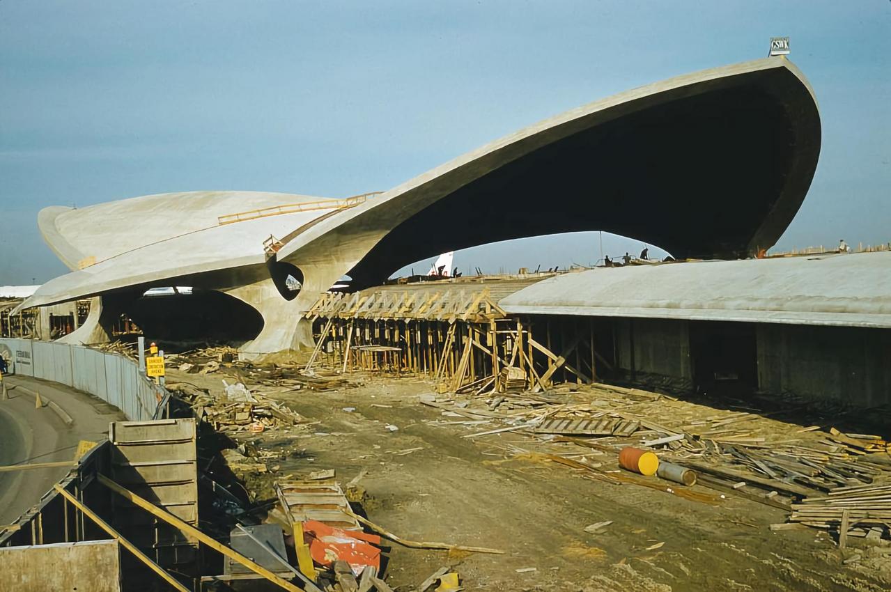
Figure 2: TWA Terminal Building under construction—New York, USA (thin shell concrete structure built using ‘conventional’ hard forms, false work, and shoring)
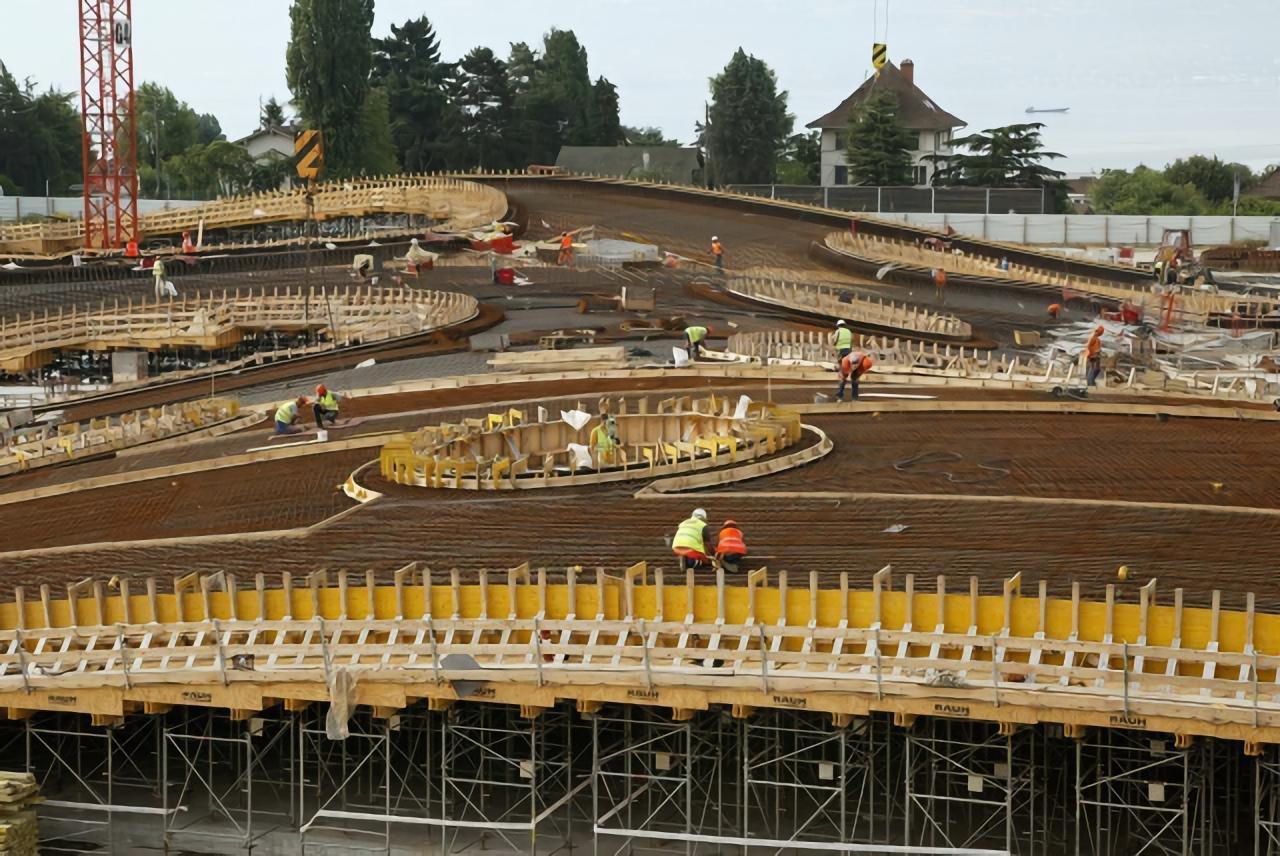
Figure 3: Rolex Learning Center under construction—Lausanne, Switzerland (concrete shell structure built using ‘conventional’ rigid forms, falsework, and shoring)
2. Air Supported Forms for Thin-Shell Concrete Shells—A Brief History
Systems utilizing inflated/air-supported fabric forms for concrete shells have been effectively used to build thousands of structures. In the last century there have been several pioneering efforts to develop and commercially use air-supported forms (sometimes called pneumatic forms or simply air-forms). Given the structural efficiency of doubly curved geometry, and the constraints of flexible form behavior under positive pressures, most of these structures were of a dome shape (or series of domes). The following is a brief history of some of the most notable participants and advances in air-forming concrete thin-shells.
2.1 Wallace Neff—Concrete applied over an air supported form:
In 1943 Neff conceptualized an air-supported form for a concrete shell home, and in 1942 he built his first “pneumatic house based on a balloon form.”1 Neff was granted a patent for this approach in 1943, which described “forcibly projecting or ‘shooting’ wet concrete over a large-size pneumatic form to build up thereon a continuous layer of concrete which on setting provides a self-sustaining concrete shell….”2 Over 1,600 of Neff’s bubble houses would eventually be built between the 1940’s and 1950’s.
2.2 Horral Harrington—Concrete applied to the inside face of an air supported form:
Harrington’s advance was in applying concrete to the inside surface of the form, and with an embedded wire network, prestress the concrete shell. He received a patent for this approach in 1964.3 Harrington would later start two successive companies and build a number of post tensioned domes between the 1970s and 1990s, though typically these structures would be sprayed with shotcrete on the outside of the inflated form.4 Many of Harrington’s structures were built in the United States Midwest for the storage of road salts.
2.3 Lloyd Turner—Applying plastic foams to an air supported form:
Turner obtained a patent in 1966 relating to “structures erected by spraying a plastic foam or like material against pneumatically inflated forms.” Turner’s primary claim was “allowing the plastic foam to harden and become rigid and self-supporting.”5 Although the innovation was the application of plastic foam against an air-supported form to create a structure, Turner later included the application of concrete as part of his buildings and many of his structures have been built using only lightweight concrete.6 Turner’s efforts have primarily been residential structures.
2.4 Dante Bini—Lifting wet concrete into a shell shape using air supported forms:
Bini experimented with air supported forms in a reverse manner to Neff, Harrington, and Turner, in that the placement of materials came prior to final forming. This approach required wet concrete materials and expandable reinforcing members to be placed on top of a flattened flexible form, then inflating “the hardenable building material into the desired shape.”7 This system was granted a patent in 1969 and has since been used to create over 1600 structures through his company BiniShells, with the largest being 38m in diameter.8
2.5 Haim Heifetz—Improvements in form reusability:
Heifetz efforts were primarily directed in the economical use/reuse of PVC forms. Particular interest was in the development of a base ring that would maintain the form’s design shape, and also be easily removable and reusable. Heifetz received a patent for these efforts in 1972.9 Heifetz’s shells were reinforced on the exterior of the airform and sprayed with cementitious materials, which through his company Domecrete, later included proprietary lightweight concrete materials.10
2.6 Heinz Isler—Optimized shell forms and increased spans:
Isler had early successes in proposing new ways to form shells.11 Isler created partial and full scale models of many air-supported forms,12 and co-founded the company Bubble System AG to commercialize concrete shells. In 1977 he was granted a patent for some of these ideas,13 with most of his more than 600 concrete shells utilizing air supported forms built by the end of the 1970’s.14
2.7 David, Barry, and Randy South—integrated form-foam-concrete with uniform shell composition:
David South was intrigued by the work of Buckminster Fuller and efficient geometries, specifically, the nature of spherical shapes optimizing the volume-to-surface-area ratio.15 South had interests in building large diameter spherical shapes (domes), expecting that low surface area ratios would yield lower material use and overall construction costs. David, with his brothers Barry and Randy South owned a company that specialized in the application of spray polyurethane foam (SPF) insulation. Often cementitious materials were sprayed over the SPF as a fire barrier. The combination of SPF with cementitious coatings increased building rigidity and structural capacity. Using fast-set SPF as a semi-rigid material to support layers of load-bearing shotcrete (spray-applied wet-mixed concrete) in dome shapes, the Souths began experimenting with air-supported forms. The Souths soon after started the company Monolithic Constructors to build what they termed Monolithic Domes, a combination of spray foam insulation with embedded wires to support reinforcing steel and guide depth control of spray-applied wet-mix concrete (shotcrete).16 In 1979 a patent was issued for this system.17
The advances above capture some of the most significant approaches to constructing air-supported thin- shell concrete structures. Other incremental innovations and experimentation by these same individuals, and many other researchers, architects, engineers, and builders, have continued a persistent inquiry into air-forming concrete thin-shell structures.18 For example, one approach in the last decade lifts and forms hardened concrete plates into a shell structure using a pneumatic form.19 Another recent system uses fiber-based fabrics with impregnated dry cementitious materials, which are inflated into shape and sprayed with water to activate/harden the shell.20 However, despite nearly 100 years of effort by many inventors, designers, and builders, the number of thin-shell concrete structures built using air-supported forms remains relatively low.
3. Current State-of-Practice
3.1 Monolithic Domes
In most cases air-supported forms are the only economically feasible way to build concrete shells,12 and of the various iterations in the last century, the Monolithic Dome (MD) system is currently the predominant method of constructing air-formed concrete shells. Since the late 1970’s the MD industry has produced an estimated 2500–3000 concrete shell structures internationally, with an approximate total ground area of 1.2M–1.7M m2 (see table 1). These structures have been concentrated in the United States, though it is estimated that an additional 50-70 countries also have MD structures (see figure 4). As of 2021 there have been at least ten known companies (7-US headquartered, 3-European headquartered) that have constructed 30 or more MD shell structures, with these companies having been in operation for an average of 27 years. There are an additional 20 companies that have constructed between 5–29 MD structures, and more than 300 individuals who have constructed at least 1 (generally small scale <15m diameter) MD shells.21 It is estimated that the 2021 commercial global market for MD construction was between 60M–90M USD (contract costs for design and construction of concrete shell superstructures and supporting foundations only).
Given the current prevalence of the MD approach for constructing air-supported concrete thin-shells, this paper focuses on MDs as a matter of practicality and data access. Though other approaches may embody many or all of the same attributes. The research utilizes a proprietary database of projects, organizations, and structures compiled by the Monolithic Dome Institute to establish a baseline.21 These data were compared against grey literature to help clean the raw data set, then to make estimations of typical project parameters, total numbers of MD shells constructed, distributions of structures by building sector, and proportional values of shell structure ground area covered.
3.2 Shift in Building Sectors and Sizes
In the early days of concrete shell construction using air supported forms, typical use cases were detached residential structures. Between Neff, Bini, Haifetz, and Isler, thousands of concrete thin-shell were constructed, predominantly for low-cost housing units. These structures generally had a diameter of <15m (ground area <178m²). While the largest number of modern air-supported concrete shell structures continue to be used for single detached residential units, industrial and commercial structures make up over 80% of the market for concrete thin-shell structures by estimated contract value. Today industrial and commercial applications appear to have the most market potential. The normalized average ground area for industrial and commercial concrete shells using air-supported forms is approximately 1400m². Owing to the structural capacity of free-span concrete thin-shell dome structures, the speed and efficiency of the integrated air-form as both structural form and final roofing membrane, and the structure’s resilience against extreme weather events (due to efficient geometry coupled with thermally protected reinforced concrete), the application of domes as dry-bulk storage structures continues.22 Additionally, the marginal increase in cost to develop a FEMA (Federal Emergency Management Agency) design compliant structure using a concrete shell vs. other traditional structures suggests this trend will continue.23
4. Benefits
Why have concrete thin-shells persisted over the last 100 years? This motivating question for the current research led to the identification of advantages distilled from hundreds of pages of marketing materials from MD design and construction companies currently in operations. Primary advantages are as follows:
- Speed of construction—shortened construction time and general cost savings
- Controlled construction environment—elimination of some weather-related construction delays
- Material utilization efficiencies—reduced construction cost and lower embodied carbon
- Reduced waste stream—spray-in-place construction supports waste reduction
- Thermal efficiencies—operational cost savings and operational carbon reductions
- Design flexibility—free span design
- Resilient structure performance—improved life-cycle value
4.1 Efficient use of Materials, Equipment, and Labor
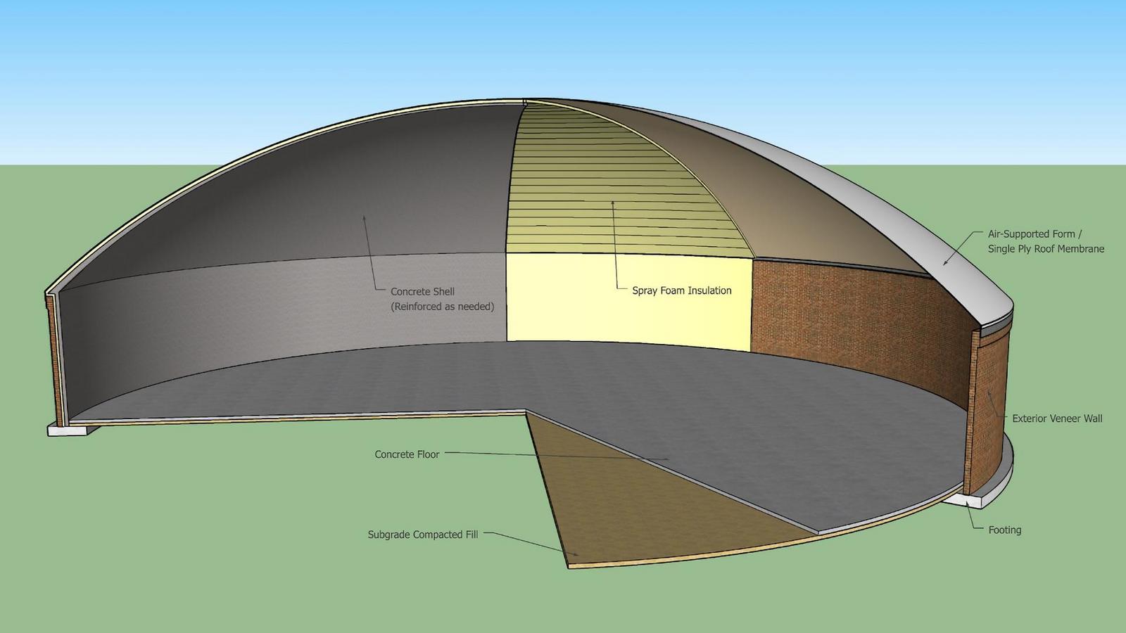
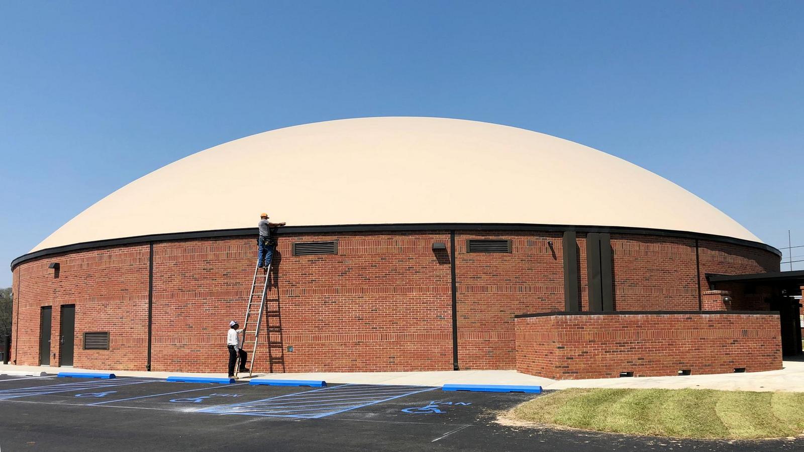
Air-supported forming of concrete shells is efficient in material-utilization. Only a small quantity of waste is generated during construction of the structure (an optimized pairing of geometry and material selection), which by design requires relatively small amounts of building materials per unit volume of enclosed space. Additionally, no temporary forms are used in these structures, as the shell’s flexible exterior “skin” or single ply membrane is also the form (Figure 5). Neither is there any required ‘false-work,’ as air pressure is used to keep the final membrane/form supported until the concrete is applied.
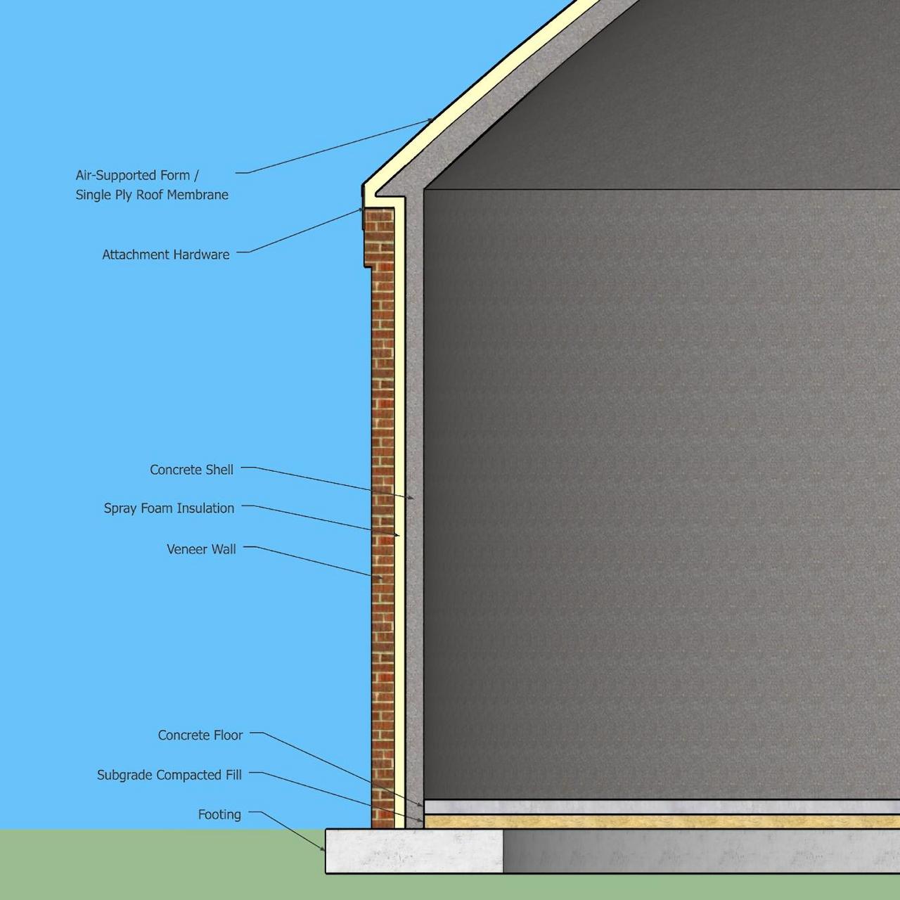
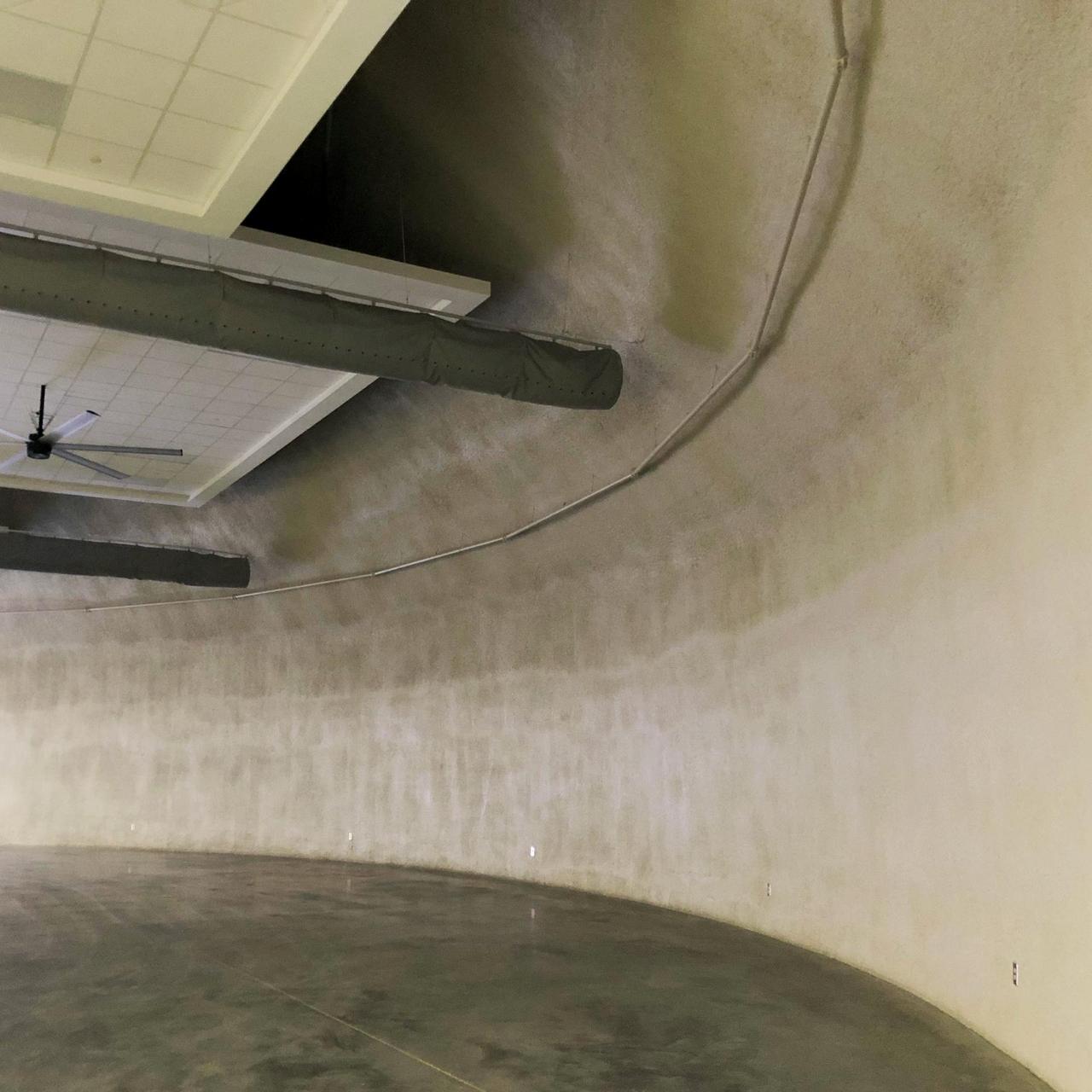
Spray polyurethane foam materials are typically incorporated between the PVC membrane, and the interior concrete/shotcrete shell, which creates a seamless insulative envelope with little construction waste due to direct-surface application (Figure 6 and 7). The load bearing shell, created from spray-applied (shotcrete), optimizes the material performance of concrete (compression) by virtue of the shell’s geometry. Hence the volume of concrete relative to the constructed area is rather small. Additionally, the low working stresses of concrete in these shells can provide flexibility to accommodate a wide range of material mixes, which can be locally sourced virtually anywhere across the globe. Cementitious mixes can also incorporate high amounts of waste stream products such as powdered ash and recycled aggregates. Additionally, the material efficiency of air-supported concrete domes provides sustainability benefits from a smaller embodied carbon footprint per volume/area of constructed space.
Air-formed construction of concrete domes/shells is also a labor efficient process. Relative to the size of structures, a small crew of skilled and semi-skilled builders can construct large structures in short time frames, within a controlled environment protected from the exterior elements. Thus, the total number of labor hours per unit of surface area (or enclosed space) is quite low, with minimal delays due to weather. Equipment utilization rates per volume of space are also low.
4.2 Thermal Efficiencies of Thin-Shell Concrete Structures with Exterior Insulation
Concrete thin-shell structures, when coupled with exterior insulation layers, maximize building thermal performance through heat load shifting with thermal mass and optimized building envelope composition. For many use cases, the diurnal interior and exterior heating/cooling loads can be balanced for reduced impact through heat load shifting and basic passive design principles from the last century.24 High volumes of exposed concrete mass in the dome roof (primarily), and often exposed mass of walls and floor can absorb and release significant quantities of heat. A large internal volume of space is also leveraged for mass air movement (natural and mechanically assisted convection) to optimize the structures’ heat-load carrying capacity depending on internal occupant loading. Passive and low energy active heat load shifting through mass air movement reduces both capital costs and operating costs, along with lower total levels of operational carbon.
As previously illustrated, a seamless layer of insulation, typically spray polyurethane foam (SPF), is incorporated with such shells (e.g. MDs) (Figure 8). An exterior thermal barrier maximizes the concrete’s heat load capacity and prevents thermal bridging through structural materials. The attributes of SPF, in addition to high thermal resistance values (R-values), is an optional closed-cell variant, providing an effective air barrier to prevent unwanted air movement between interior and exterior spaces (e.g. air infiltration, draft, leakage).
4.3 Design Flexibility and Free Span Construction
The nonstandard appearance of concrete thin-shell domes is sometimes viewed as undesirable. Concrete thin-shell domes have an obviously distinct shape that is different from rectilinear forms and shapes that dominate the built environment, which can be considered ‘unfit’ for existing architectural aesthetic styles. Adjustments to shape, for example the combination of doubly curved spherical caps inflated and/or constructed with singly curved cylindrical walls, have been used to increase a degree of interior space utilization, and more subtle connection with surrounding building styles. New advances in air-forming technology have begun to open the door for new forms and shapes.
5. Barriers to Adoption
With the exception of a few niche industries (e.g. industrial dry bulk storage), concrete thin-shell structures have not achieved strong market penetration despite a range of potential advantages. The final section of this paper outlines several conceptual barriers to adoption and provides a set of areas for future scholarship in an attempt to reinvigorate inquiry toward unlocking the potential economic, sustainability, and resiliency benefits purported in the concrete thin-shell community.
5.1 Geometry and Air-Forming
One obvious barrier of adoption is the geometric constraints of air-forming. Given the nature of air-inflated and air-supported forms, the vast majority of such structures have been simple spherical sections and oblate ellipsoids, sometimes in combination with cylindrical sections. These myriad of “dome” shapes are also some of the most structurally efficient (and thus cost efficient). While there is much scholarship in the area of form finding for efficient geometric shapes,11 there is little research connecting optimal shapes with the full extent of economical air-forming practices. With much of modern air-forming design (as well as structural analysis of final shapes) occurring in digital models, it is much easier to run various iterations of air-forming potentials for new and unique shapes. This is one area of further inquiry, ripe for study.
5.2 Empirical Data on Economic Benefits
Another barrier to adoption may be the dearth of empirical information on economic benefits of concrete thin-shells using air-supported forms. For example, there exists much anecdotal data on the improved thermal energy performance of exteriorly insulated concrete thin shell structures, sometimes with claims of HVAC energy cost reduction of 30%-90%. However, there is little in the way of rigorous studies to validate these claims. Additionally, some work has been conducted to show comparable structural systems cost modeling for FEMA rated-storm shelters,23 but general comparisons in various construction projects are difficult to identify because the system for building concrete shells with air-supported forms is not published in standard estimating databases and construction cost indices. Additional inquiry in comparative construction economics is therefore necessary.
5.3 Life-Cycle Performance
Sustainability and resiliency claims of concrete thin-shell domes are increasingly noted. However, there is yet to be any significant life-cycle cost analysis for concrete shell structures using air supported forms. Efforts to establish total effects of waste stream diversion, deviations from embodied and operation carbon footprint baselines, and projected performance and maintenance requirements in various extreme load conditions for life-cycle analysis are needed.
5.4 Undefined Architectural Challenges
Finally, it has been repeatedly suggested that there are a range of architectural challenges relating to what forms best meet clients’ needs and what is “beautiful.”25 This is an area of limited anecdotes and scans of current practice which have led the discussion on the fitness of concrete shell structures in the built environment. There is virtually no systematic qualitative inquiry into architectural education and professional practice to clearly illustrate the degree to which architects are aware of concrete shells and their makeup, as well as their economic, sustainability, and resiliency characteristics and advantages. This is perhaps the largest barrier in our understanding of why concrete shell structures have not seen more widespread adoption—another area for further study.
6. Conclusion
Since the 1930s, when some of the first cases of air-formed structures were conceptualized, there has been persistent interest in this approach to constructing concrete thin-shell structures. Multiple individuals have participated in various iterations of current approaches, and there are new approaches being considered even in the last decade. In the last 100 years there have been some 10,000 structures completed, with a trend from small residential units to larger commercial and industrial shells. The overall market for concrete thin-shell structures using air-supported forms continues to grow, however at a nominal scale.
This design and construction method proposes a set of potential benefits, including high energy efficiency, low material waste, an optimized geometry and structural system for sustainable and resilient building performance, improved life-cycle assessment, and overall building value. However, with modest market growth in 40 years, it seems evident that significant barriers continue to exist for further adoption. This paper proposes that additional scholarship and inquiry is needed in the areas of;
- evaluating practical air forming techniques with optimized form finding approaches,
- empirical studies in building performance due to envelope efficiencies for modeling cost savings and embodied/operational carbon footprint reductions,
- documented system cost comparisons to identify deltas against ‘conventional’ systems,
- architectural perspectives in educational and professional practices related to concrete shells as building envelopes.
This paper serves as a call for an expansion of interdisciplinary research to better understand the economic, social, structural, architectural, and sustainable attributes (and their intersections) with respect to the use of air-supported forms for the construction of concrete thin-shell structures.
Acknowledgements
This research was made possible by data access from the Monolithic Dome Institute’s proprietary commercial database. The authors are grateful to multiple companies currently involved in the construction of concrete thin-shell structures for their insights and contributions to the author’s database.
References
- J. Head, No Nails, No Lumber: The Bubble Houses of Wallace Neff. New York: Princeton Architectural Press, 2012. ↩︎
- W. Neff, “Building Construction,” USA Patent Appl. 2335300, 1943. ↩︎
- H. Harrington, “Method and Apparatus for Constructing a Concrete Structure,” USA Patent Appl. 3118010, 1964. ↩︎
- M. K. Hurd, “Post-tensioned dome shotcreted from outside an inflated form,” Concrete Construction, vol. 34, Apr. 1988. ↩︎
- L. Turner, “Method of Molding a Building Structure by Spraying a Foamed Plastic on the Inside of an Inflateable Form,” USA Patent Appl. 3277219, 1966. ↩︎
- L. Turner. “Flying Concrete; structural and sculptural forms in light weight concrete.” http://www.flyingconcrete.com/lloyd-turner.html (accessed May, 2022). ↩︎
- D. Bini, “Method for Erecting Structures,” USA Patent Appl. 3462521, 1969. ↩︎
- W. McLean, “The Pneumatically Powered Construction Systems of Dante Bini,” in Further Studies in the History of Construction: the Proceedings of the Third Annual Conference of the Construction History Society, University of Cambridge, J. B. Campbell, Nicholas; Driver, Michael; Heaton, Michael; Pan, Yiting; Tutton, Michael; Wall, Christine; Yeomans, David, Ed., 2016: Construction History Society, pp. 441-450. ↩︎
- H. Heifetz, “Inflatable Forms,” USA Patent Appl. 3643910, 1972. ↩︎
- YSM. “DOMECRETE Building System.” http://ysmforbuilding.com/en/domecrete-domes-building-system/ (accessed Jun, 2022). ↩︎
- S. Adriaenssens, P. Block, D. Veenendaal, and C. Williams, Shell Structures for Architecture: Form Finding and Optimization. New York: Taylor & Francis, 2014. ↩︎
- I. Mungan and J. F. Abel, Fifty Years of Progress for Shell and Spatial Structures: In Celebration of the 50th Anniversary Jubilee of the IASS (1959-2009). Madrid: International Association for Shell and Spatial Structures, 2011. ↩︎
- H. Isler, “Hall Construction with Vaulted Roof,” Germany Patent Appl. 1709351, 1977. ↩︎
- M. Beckh and G. Boller, “Building with air: Heinz Isler’s bubble houses and the use of pneumatic construction techniques,” presented at the Conference: Sixth Conference of the Construction History Society, Cambridge, UK, 2019. ↩︎
- A. C. Edmondson, A Fuller Explanation: The Synergetic Geometry of R. Buckminster Fuller (Design Science Collection). Boston: Birkhäuser, 2012. ↩︎
- F. Parker, Think Round: the story of David B. South and the Monolithic Dome. Italy, TX: Monolithic Dome Institute, 2004. ↩︎
- D. South and B. South, “Building Structure and Method of Making Same,” Patent Appl. 4155967, 1979. ↩︎
- B. Kromoser and P. Huber, “Pneumatic formwork systems in structural engineering,” Advances in Materials Science and Engineering, vol. 2016, 2016. ↩︎
- B. Kromoser and J. Kollegger, “Pneumatic forming of hardened concrete—building shells in the 21st century,” Structural Concrete, vol. 16, no. 2, pp. 161-171, 2015. ↩︎
- Concrete Canvas. “What Are CC Shelters.” https://www.concretecanvas.com/us/cc-shelters/ (accessed May, 2022). ↩︎
- MDI. RoundtableCRM, Monolithic Dome Institute, 2022. ↩︎
- S. J. Ramos, “Materiality in the seam space: Sketches for a transitional port city dome district,” Urban Planning, vol. 6, no. 3, pp. 210-222, 2021. ↩︎
- C. Zweifel and A. South, “Concrete Dome Structures and Extreme Wind Loads: The Design of Community Shelters,” in Shells, Membranes and Spatial Structures: Proceedings of IASS-SLTE 2014 Symposium, Brasilia, Brazil, R. Brasil and R. Pauletti, Eds., September 15-19 2014. ↩︎
- P . Niles and K. Haggard, “Passive Solar Handbook,” California Energy Commission, Sacramento, CA, 1980. ↩︎
- C. Meyer and M. Sheer, “Do concrete shells deserve another look?,” Concrete international, vol. 27, no. 10, pp. 43-50, 2005. ↩︎
Copyright
Copyright © 2022 by Andrew J. South. Published with permission. Originally published by the International Association for Shell and Spacial Structures (IASS) and Asian-Pacific Conference on Shell and Spacial Structures (APCS).


