Disaster Survivability of Thin-Shell Concrete Dome Structures: Experience and Practice
Andrew SOUTH—Department of Civil and Environmental Engineering, Stanford University
Chris ZWEIFEL, P.E., S.E.—ZZ Consulting in Shelley, Idaho
Abstract
Concrete thin-shell domes constructed using air-supported forms are increasingly built for a variety of uses. A number of these structures have experienced extreme natural events including hurricanes, earthquakes, and tornados. We provide evaluations of loads applied to these structures based on reported forces during the events and analyze building performance. We compare this theoretical analysis to reports of building survivability from owners and users of the structures after event occurrence. We determine that in most cases the loads experienced do not approach minimum practical design loads, and identify special considerations for designers.
Keywords: Concrete shells, dome, disaster resistance, Monolithic
Table of Contents
- Introduction
- A Condensed History
- Disasters and Extreme Loads
- Design and Engineering Considerations
- Extreme Loadings—Hurricanes
- Extreme Loadings—Earthquakes
- Extreme Loadings—Tornados
- Conclusion
- Acknowledgments
- References
- Copyright
1. Introduction
The purpose of this paper is to illustrate aspects of thin-shell concrete domes in the face of extreme loads developed as a consequence of natural disasters. As the frequency and intensity of disasters appear to be increasing, the importance of disaster-resistant structures becomes more important. This paper is intended to be a high-level introduction to social, technical, and economic aspects of thin-shell construction for design professionals, builders, public and private owners, and academics interested in orienting themselves to a relatively under-investigated building envelope system.
2. A Condensed History
Concrete shell structures have never found a dominant place in the built environment as a structural system for the design and construction of any building class or type, despite a rich history of pioneering efforts by many designers and builders, a host of distinct structure examples, and a persistent cadre of academics and professionals who continue to study, design, and construct concrete shell structures. It should be noted that some exceptions may be taken for certain types of liquid and dry bulk storage facilities employing concrete shells (i.e. silos and domes), and historically the use of natural draft cooling towers at some types of electric power generation facilities. Post World War II conditions, particularly in Europe, were right for a surge of interest in and the production of concrete shell structures (specifically, a need for significant reconstruction efforts and therefore buildings, relatively low labor costs, and short supplies of construction material stocks). However, after two decades of successes shell design and construction almost completely ended Peerdeman.1
Several factors, generally attributable to an increase in overall project costs, likely contributed to this result. The novelty of various shapes and forms generally requires complicated engineering analysis, which may include laborious computer and even physical modeling. Approving authorities and other construction oversight bodies often face difficulty in performing review and inspection procedures, as unfamiliar details and work practices are used in plans and construction work, which has the tendency to increase project overheads and/or reduce overall project profitability for organizations involved in a project. Concrete shell structures often employ non-standard forming techniques, which increases overall project costs as forming materials are traditionally not reliably scalable within or across projects. Equipment necessary to construct concrete shells is also typically an adaptation of equipment purposively designed for alternate structure types, thus decreasing efficiencies in construction. Such structures can also include a higher degree of difficulty for construction teams, limiting the numbers of skilled labor pools available to do the work, naturally introducing cost premiums from contractors, subcontractors, and suppliers at multiple tiers in the project value chain.
It should also be noted that these factors are generally presented as an extension of primary economic theories of scalability such as those outlined in introductory texts of basic economic principles O'Sullivan, et al.2 However, a network theoretic argument can also be made on the premise that owners, designers, and builders may not be sufficiently networked to allow early project ideas and requirements to develop a “conceptual foothold,” they lack the necessary connections (i.e. social networks) to professional expertise that could aid in incubating a novel design concept Granovetter.3 Some of the earliest and most influential design decisions are based on an individual’s ability to “make a project a reality” through their dependencies on other networked actors in the project development value chain. For example, a project owner may approach a designer with ideas of a novel project concept (e.g. a concrete shell system), only to have the designer recognize that there exists no professional experience in the designer’s network (e.g. structural engineers, builders, development consultants), to produce sufficient confidence that such a project could be delivered should the building concept find favor.
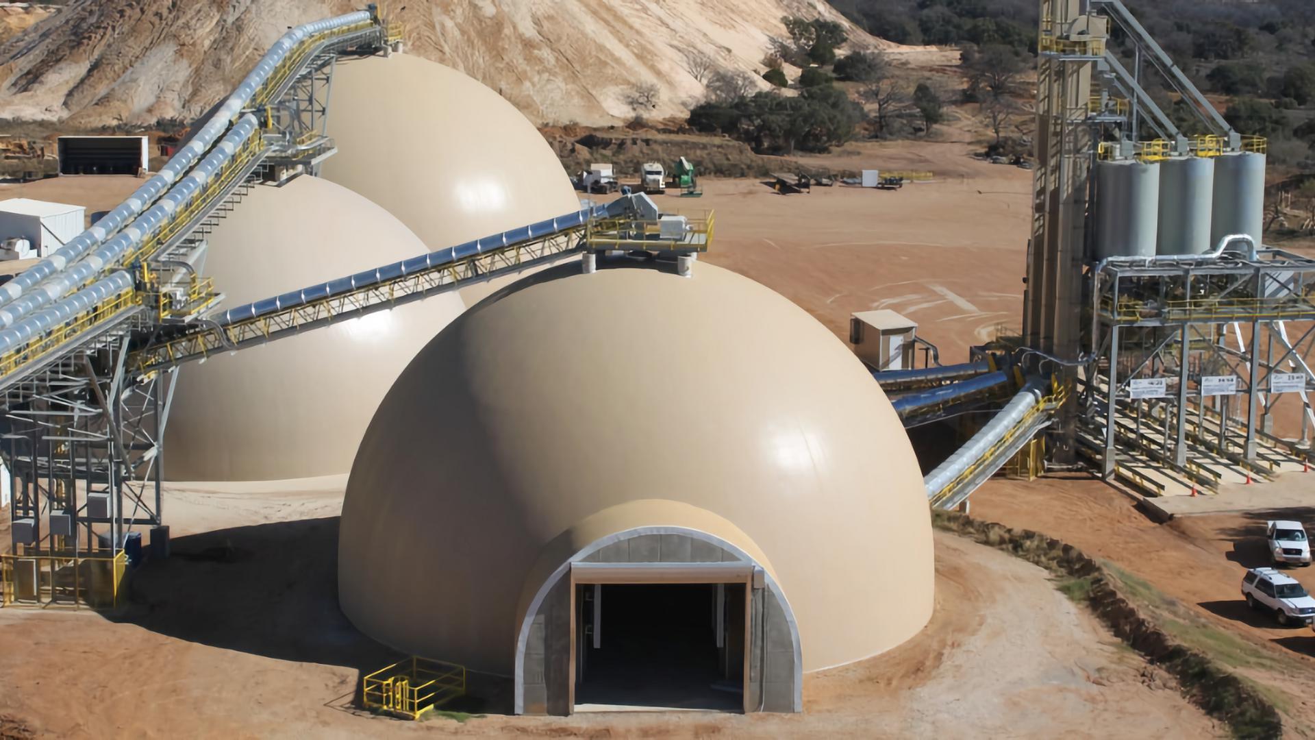
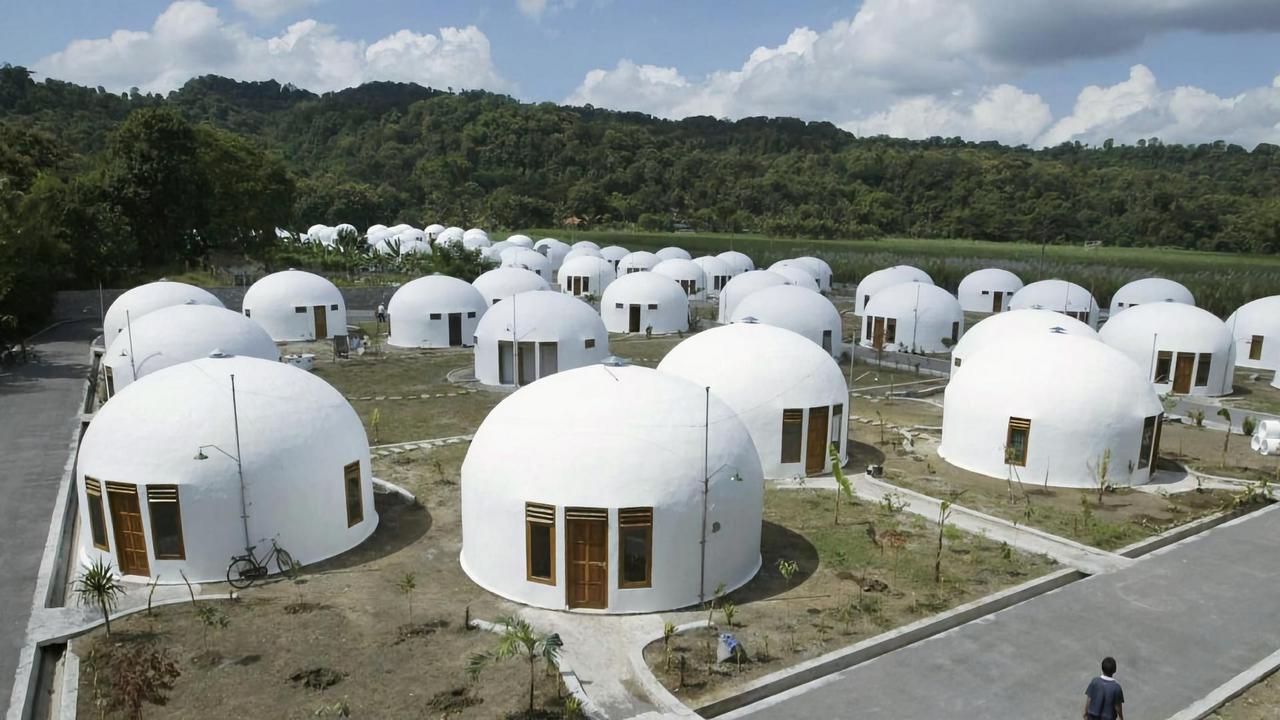
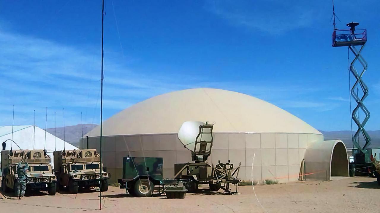
Despite typical economic constraints (and potential network constraints), concrete shell structures continue to be designed and built for a variety of uses. In the last decade alone thin-shell structures have been built to serve various uses, including industrial facilities, commercial buildings, architectural structures, custom single-family residences, and low-income housing. Figures 1-5 illustrate examples.
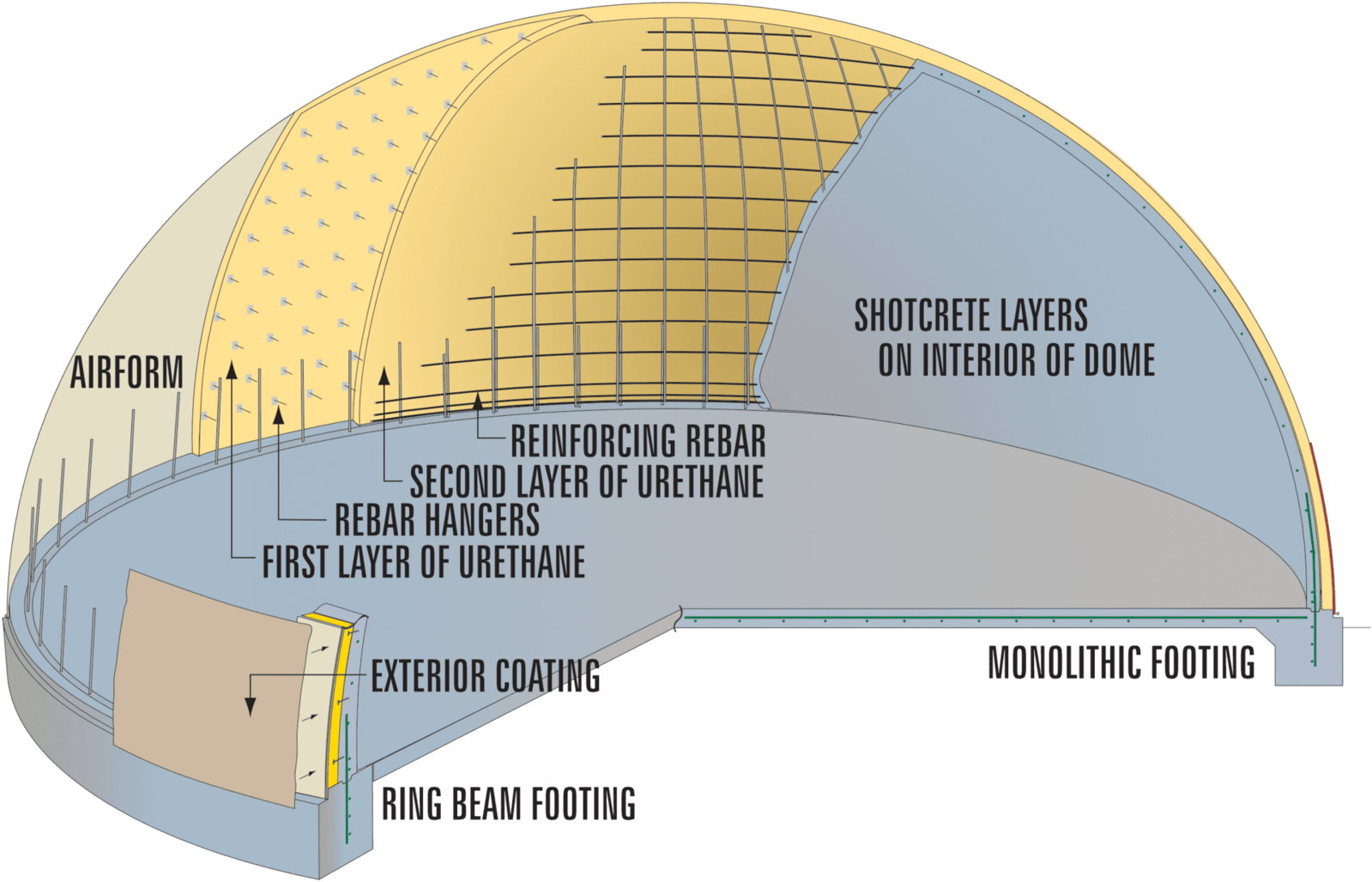
The Monolithic process for constructing dome shells and other single and double curved structures is perhaps the most commercially successful method for the construction of thin-shelled structures. This paper draws specifically from examples of thin-shells constructed using the Monolithic process. Since its original conception in 1976, thousands of thin-shelled structures have been designed and constructed for the uses mentioned above. The Monolithic process is characterized by the application of structural and nonstructural building materials in conjunction with continuously shaped air-supported forms. A “typical” Monolithic dome process can be simplified into five steps ACI 3344 (see figure 6):
- Structural Footing—A concrete ring-beam footing is designed and constructed to function as a spread footing for the structure, and to offer partial resistance (along with the lower zone of the shell at the footing connection) of the tensile forces concentrating at the base of the dome structure.
- Air-Supported Form (air-form)—A tensile fabric membrane, previously designed and manufactured offsite, is continuously attached to the footing and inflated with high-volume fans to create the shape and profile of the structure. The air-form membrane is kept at constant pressure, as designed by the membrane manufacturer. This fabric membrane is both a means of forming the structure and serves as the final single-ply protective roof membrane for the structure. The fans run continuously throughout the construction of the shell until the structure is able to support its own load plus an acceptable factor of safety.
- Spray Polyurethane Foam (SPF)—Multiple layers of medium-high density SPF insulation are applied to the interior surface of the fabric membrane to a) give partial rigidity to the structure, b) provide a means to support subsequent steel reinforcing and shotcrete application processes, and c) serve as the structures’ required/designed insulation layer. As this step (and all other steps performed while the dome is “under pressure”), a double partition airlock is used for labor and material resources to enter and exit the structure while maintaining the design air pressure.
- Reinforcing—Reinforcing bars (rebar) are attached to wire hangars (rebar hangers) embedded in the SPF along with a project-specific layout of horizontal and radial (meridian) grid lines. This reinforcing layout is engineered for the appropriate loading conditions.
- Shotcrete—Shotcrete, a spray application of wet-mixed portland cement-based concrete, is applied in layers from the bottom of the dome upwards in concentric “zones”. The reinforcing and shotcrete layers are not placed consecutively but in offset parallel processes, such that layers of reinforcing steel are embedded to a specified depth prior to additional layers of reinforcing steel in zones above.
Despite the successes of Monolithic “air-formed” thin-shell structures and other similar air-formed variants, the speed of adoption for concrete shell structures remains quite slow. Primarily supposed to be an aspect of project economics (i.e. concrete shell structures cost more per area and/or volume of enclosed space), but also likely a result of the stylistic association from the 1950s-1960s time period in contrast to modern architectural themes of the built environment Peerdeman [1]. The exception is taken with industrial facilities where concrete shell structures have repeatedly demonstrated sufficient life-cycle performance value to become accepted as a significant element in the built environment, and where structural form and general architectural congruity are likely to be evaluated differently. In recent decades, however, another aspect of thin-shell structures has been repeatedly highlighted, an ability to perform under extreme loads introduced via natural disasters. This characteristic of “disaster survivability” has been tested unintentionally, and is evaluated across three cases in this paper.
3. Disasters and Extreme Loads
The concept of disaster is often perceived quite differently, with multiple methods for defining and classifying disasters Quarantelli,5 Perry and Quarantelli.6 There is some agreement that disasters are inherently social, in that they affect humans and their patterns and modes of interaction. Thus disasters are often categorized by the way in which they affect individuals, communities, and societies. It is important to note that the design professions directly influence how disasters affect humans. “….planners, architects, and engineers manipulate us every day. We live the way we do because they have created the living conditions” Ramroth.7 This can be extended to include policymakers—developing codes and standards, and builders—combing resources to physically produce the tangible built environment. This connection between the social world and the deterministic disciplines of design and construction is critical to emphasize, as it motivates this line of research and the responsibilities professionals in these disciplines inherently assume. Particularly with respect to the potential consequences of disasters, as are continually evident in daily international media outlets.
However, for the purposes of this paper, we categorize disasters by their cause, as a means for identifying the loads applied to concrete shells. For example, an EF4 tornado Edwards, et al.8 and a SSHWS category 5 hurricane (Saffir-Simpson Hurricane Wind Scale) NOAA9 will have dramatically different social consequences to individuals and communities, but produce relatively similar wind speeds and similarly applied wind loads to structures. We acknowledge that disasters can be grouped according to natural or manmade/technological processes, and that often the two intersect. For example, a tornado event affecting the natural and built environment does so through the medium of high winds and flying debris. That debris often contains components of the built environment (building materials, machinery, etc.), which alters and even amplifies the impacts of the event. An exhaustive list of both technological and natural disasters is not necessary here, and while each disaster-causing event has unique and interesting characteristics, we specifically present extreme loads created as a consequence of high wind and seismic disaster events.
4. Design and Engineering Considerations
Prior to evaluating the engineering considerations of disaster-induced extreme loadings, a simplified characterization of the primary design considerations for concrete shells is warranted. The following load conditions represent typical aspects of shell analysis IASS WG5:10
- Dead Load (DL), minimum by governing jurisdictional code
- Live Load (LL), minimum by governing jurisdictional code
- Snow Loads, by region and governing jurisdictional code
- Unbalanced Snow Loads, by region and governing jurisdictional code
- Wind Loads, by region and governing jurisdictional code
- Seismic Loads, by region and governing jurisdictional code
- Temperature, Shrinkage, and Creep
- Point Loads, structure, and application-specific
Such load conditions develop the following primary forces evaluated in an engineering analysis of concrete shells Wilson11 (* Indicates controlling forces in most circumstances):
- *Hoop forces (stresses in the shell along the horizontal plane)
- *Radial forces (stresses running “vertically” along a meridian line of the shell)
- *Bending in and out of plane (particularly at the edges where discontinuities are present)
- Sheer (particularly at the edges where discontinuities are present)
- Buckling (buckling stability - particularly at the discontinuities)
As indicated by Samartin and Able,12 the use of computational engineering software for finite element analysis (FEA) is available to aid designers in evaluating load conditions and forces on concrete shells. For the purposes here however, numerical solutions such as those established for membrane theory Wilson,11 Billington13 are used for these analyses.
The following sections compare current minimum code required load conditions and shell design outputs with load conditions developed as a result of three historical natural disasters where thin-shell concrete dome structures were introduced to such extreme loadings. In each case, it is determined that minimum code requirements are sufficient to design each shell for survivability against such disastrous loadings. The code used herein is the International Building Code 2012 ICC.14
5. Extreme Loadings—Hurricanes
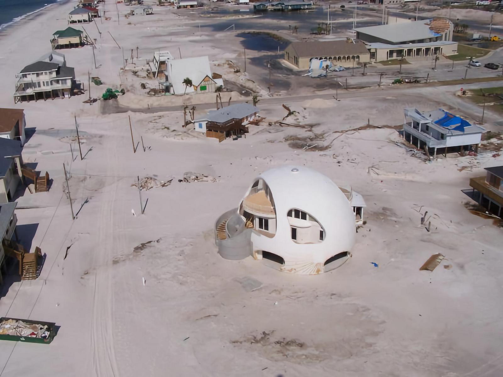
Hurricanes (tropical storms where winds reach or exceed 120 km/hr, also geographically known as cyclones and typhoons) introduce extreme loads in the form of direct high winds, wind-blown debris, storm surge (in many cases), and compounding effects from flooding. On September 26, 2004 Hurricane Ivan made landfall near Gulf Shores, Alabama with estimated peak wind speeds of 210 km/hr (category 3) NOAA.15 As cleaning and reconstruction efforts continued in the disaster-swept area, Hurricane Dennis made a partially overlapping path over the southeastern coast of the US, with peak wind speeds of 193 km/hr (category 3) NOAA.16 Both hurricanes did extensive damage along Florida’s Pensacola coastline, the area surrounding the vacation rental property known as “Dome of a Home,” a Monolithic concrete thin-shell measuring approximately 21 meters in diameter and 16 m tall (an ellipsoid) that was constructed in 2002. Of the 16 homes on the property’s half-block, 8 were either destroyed by the hurricane or damaged to the point that a complete teardown was necessary. Additional roof and water damage occurred to a number of the other adjacent homes. Damage to the domes came as the increased ocean surge tore away the home’s break-away entrance staircases (as designed) when floodwaters passed underneath and around the home (see figure 7). Minor water intrusions had seeped around doorway thresholds. During the first of the two hurricanes, the owners weathered the apex of the storm inside their home, along with a crew from NBC News.
The following satellite images illustrate the effects of the hurricane damage to properties around Dome of a Home. The concrete thin-shell is noted by the red circle in each image.
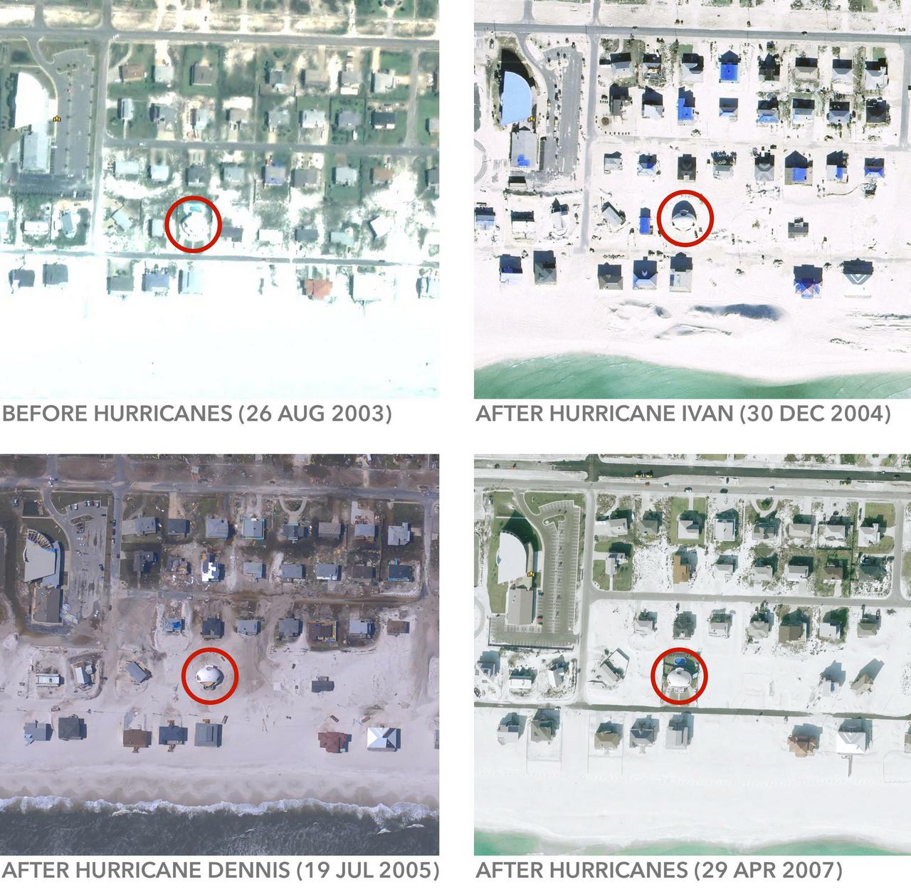
Satellite images track the progress of hurricane damage around “Dome of a Home” on Pensacola Beach, Florida, USA.
The following table (table 1) indicates a “typical” load condition and design for an elliptical concrete thin-shell dome the same size as Dome of a Home (21m diameter by 16m tall) with no additional extreme load requirements. This is compared to the potential governing loads and design appropriate of those forces produced in an extreme hurricane event. In this case a category 5 hurricane (maximally increased from the observed event). The shell concrete thickness and area of steel reinforcement are calculated using closed-form calculations for the shell section (as noted previously). This analytical design is compared to additional code-related requirements for reinforced concrete construction. Finally, concrete thickness and the proportional steel reinforcement area is given as seen in the standard practice of Monolithic thin-shell design and construction (Practical Thickness and Practical Reinforcing). For simplicity, edge conditions and special considerations for openings and penetrations in the shell are not discussed. It is apparent that the typical design of a similarly sized dome produces a shell section with adequate concrete thickness and reinforcing capable of withstanding the loads produced in a category 5 hurricane event.

Table 1: Comparative loads and design for a typical dome shell, and a Category 5 resistant dome shell
6. Extreme Loadings—Earthquakes
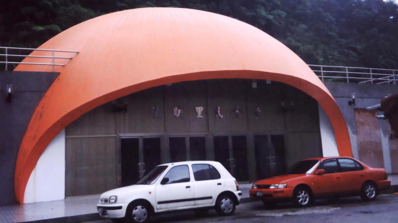
On the 21st of September 1999 an earthquake measuring 7.3 (Richter scale) hit the island of Taiwan leaving over 2,400 people dead and 11,000 injured EERI.17 In the aftermath of this event the survival of a simple 22m x 10.85m concrete thin-shell dome, previously constructed as a commercial space, came to light. The reinforced concrete buildings on either side of the dome structure were leveled in the event, while this dome suffered no structural damage (see figure 8).
The following table (table 2) indicates a “typical” load condition and design for a concrete thin-shell the same size as the above. This is compared to the potential governing loads and design appropriate of those forces produced in an 8.0 M earthquake event ASCE.18 Similar to the hurricane example, the shell concrete thickness and proportional steel reinforcement area are calculated using closed-form calculations for the shell section (as noted previously). This analytical design is compared to additional code-related requirements for concrete construction. Finally, concrete thickness and the steel reinforcement area is given as seen in the standard practice of Monolithic thin-shell design and construction. For simplicity, shell interactions and connections inside and outside the dome structure are not discussed. It is apparent that the typical design of a similarly sized dome produces a shell section with adequate concrete thickness and reinforcing capable of withstanding the loads produced in an 8.0 M earthquake event.
7. Extreme Loadings—Tornados
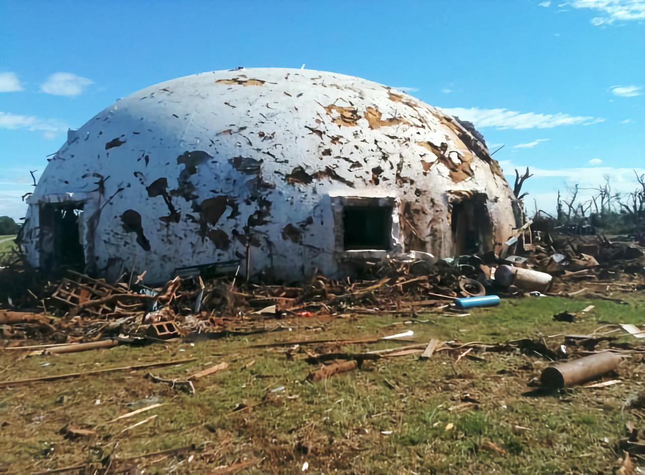
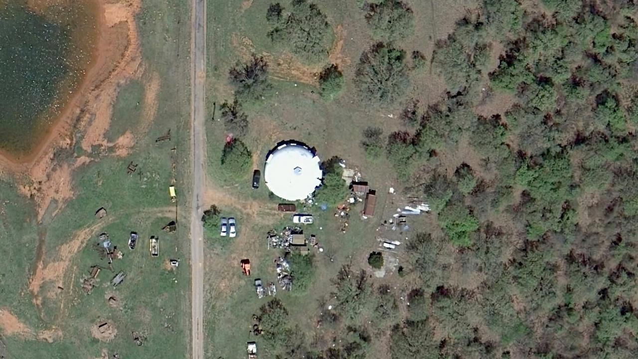
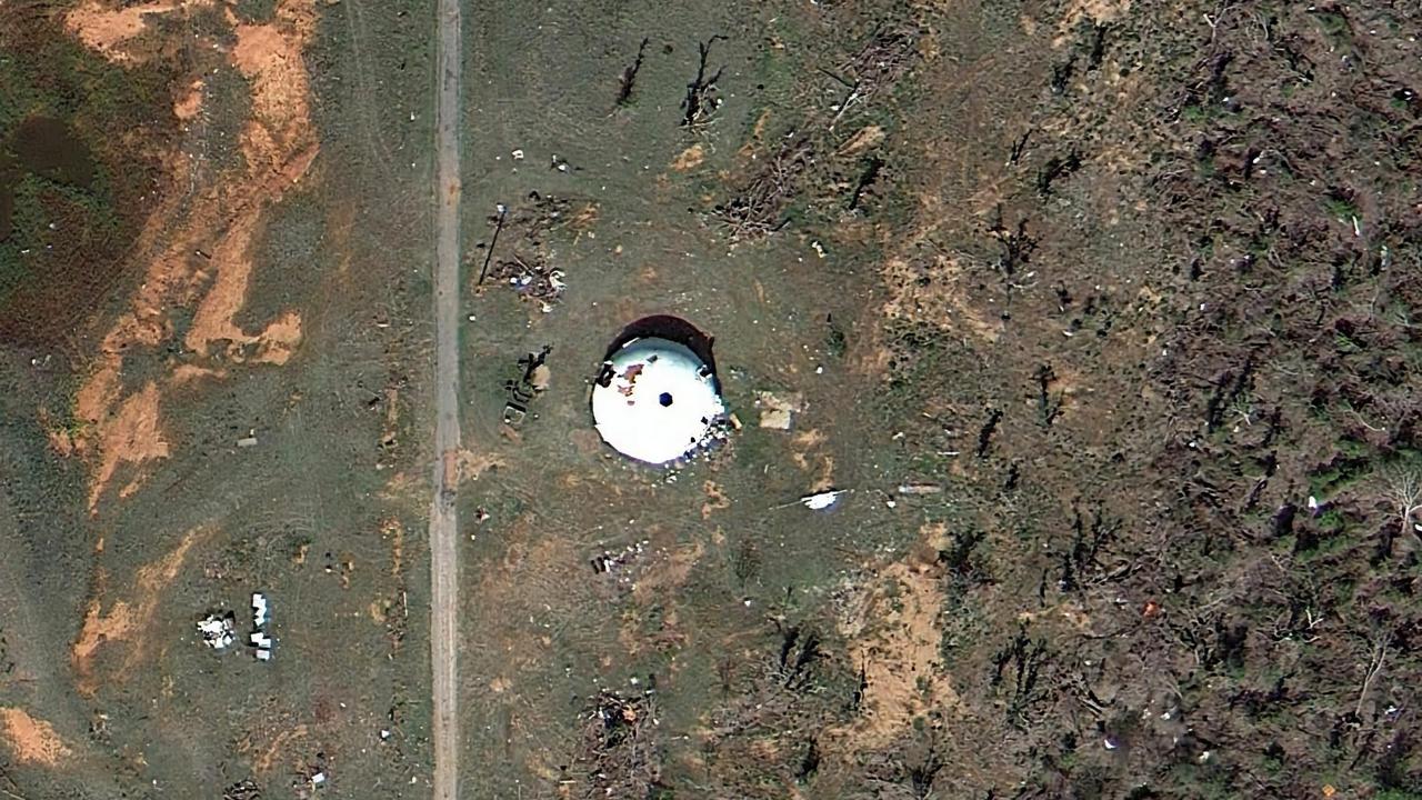
Tornados represent a particularly troubling type of disaster. They typically come with very little warning, less than 5 minutes, and can inflict massive damage via high winds and wind-blown debris. On May 24, 2011 the EF-4 Chichasha-Blanchard-Newcastle tornado event was recorded NOAA.19 This tornado traveled approximately 52km in 55 minutes with estimated peak winds of approximately 305 km/h. One 15.25m diameter by 5.5m high air-formed concrete shell constructed in the 1980s as a custom residence was directly struck by the tornado’s winds, coupled with flying natural materials (trees, vegetation, rocks, etc.), as well as multiple vehicles, a fuel tank, concrete debris, compressed gas cylinders, and other manmade objects. The owners of the residence remained inside the structure during the event, and report nearly 100% damage to the windows, skylight, and doors. The exterior of the home was badly scarred, and every door and window was blown out or otherwise destroyed. The homeowners survived. In contrast, numerous neighboring structures faced with similar direct loads were completely removed from their foundations.
The following satellite images (figures 10 and 11) illustrate the effects of the tornado damage to residence and the surrounding area. The first image was taken approximately 1 year prior to the tornado event. The second image was taken approximately six months following the event.
The following table (table 3) indicates the “typical” load condition and design for a similarly sized dome (15.25m diameter by 5.5m tall) with no extreme load requirement. This is compared to the potential governing loads and design appropriate of those forces produced from an EF-5 tornado event (maximally increased from the observed event). Using the same approach as the previous two examples, the shell concrete thickness and area of steel reinforcement are calculated for the shell section. This analytical design is compared to additional code-related requirements for concrete construction. Finally, concrete thickness and the steel reinforcing area is given as seen in the standard practice of Monolithic thin-shell design and construction. Once again edge conditions and special considerations for openings and penetrations in the shell are not discussed for simplicity. It is apparent that the typical design of a similarly sized dome produces a shell section with adequate concrete thickness and reinforcing capable of withstanding the loads produced in an EF-5 tornado event.
8. Conclusion
Natural disasters have the potential to introduce extreme load conditions for structures of all types. Regulatory bodies often provide geographic/regionally adjusted code requirements and suggestions for designers of structures in specific at-risk areas. However, it is economically infeasible to design structures capable of withstanding maximally extreme disaster events with most common building envelope systems. Thus, structures are improved by incremental improvements in design at minimal costs, but extreme natural events still pose significant risks to buildings and their occupants. The three examples above illustrate in each case that current design approaches (state-of-the-industry or Practical Design) for concrete thin-shell domes produce envelope shell sections sufficient to withstand loads produced in extreme natural disasters. Minimal shell section properties required by analysis and/or code for disaster-resistant structures are generally greater than shell design minimums allowable for typical structures.
However, practical design of concrete thin-shells (normally considerations to make shells practically constructible with generally available construction materials through commercially acceptable air-formed dome shell construction techniques ACI 334)4 produce shell sections with increased thickness and reinforcement than those of minimal allowable designs. The difference in financial cost between minimal allowable sections and practically design sections is estimated at less than 5% of building costs. In each case, the practically designed shell section for “typical” thin-shell dome structures was equal to that of shell sections designed for extreme hurricane, earthquake, and tornado events.
The cases utilized in this paper were selected based on historical performance under extreme loads from natural disasters. This necessarily limited the analysis to small diameter concrete thin-shells (<30m). Preliminary analysis of larger diameter shell structures suggests that variation between practical designs for typical shells and disaster-resistant shells increases, along with associated resource costs. However, though disaster-resistant shell structures’ unit costs may increase, they remain well below costs for more common building envelope systems meeting disaster-resistant design criteria (see companion paper by Zweifel and South in these proceedings).
This paper begins to lay an empirical foundation for concrete-thin-shell dome structures as a building envelope system that combines economical construction methods with disaster survivability. While opportunities for historical evaluations of thin-shell structures subjected to natural disasters are limited, simulated analysis of comparable structures remains a rich area for future study by the academic community. Implications for practitioners suggest that as disaster-resistant design criteria for various structures continues to become increasingly important to governments, communities, and building owners, thin-shell concrete structures (such as air-formed dome structures) are a potentially under-utilized envelope system where practical design approaches inherently produce structures capable of withstanding extreme loads from natural disasters.
Acknowledgments
The authors acknowledge appropriate image and photo credits to the Monolithic Dome Institute and other sources in the public domain as applicable.
References
- B. Peerdeman, “Analysis of Thin Concrete Shells Revisited: Opportunities due to Innovations in Materials and Analysis Methods,” Masters, Structural and Building Engineering, Delft University of Technology, Delft, Netherlands, 2008. ↩︎
- A. O'Sullivan, S. M. Sheffrin, and i. Prentice-Hall, Prentice Hall Economics: Principles in Action: Prentice Hall, 2003. ↩︎
- M. Granovetter, “The strength of weak ties,” American journal of sociology, vol. 78, p. l, 1973. ↩︎
- ACI 334, “Construction of Concrete Shells Using Inflated Forms,” ed. Farmington Hills, MI: American Concrete Institute, 2005. ↩︎
- E. L. Quarantelli, What is a Disaster?: A Dozen Perspectives on the Question: Taylor & Francis, 2005. ↩︎
- R. W. Perry and E. L. Quarantelli, What Is A Disaster: New Answers To Old Questions: Xlibris Corporation, 2005. ↩︎
- W. Ramroth, Planning for Disaster: How Natural and Manmade Disasters Shape the Built Environment: Kaplan Publishing, 2007. ↩︎
- R. Edwards, J. G. LaDue, J. T. Ferree, K. Scharfenberg, C. Maier, and W. L. Coulbourne, “Tornado Intensity Estimation: Past, Present, and Future,” Bulletin of the American Meteorological Society, vol. 94, pp. 641-653, 2013/05/01 2013. ↩︎
- NOAA, “The Saffir-Simpson Hurricane Wind Scale,” N. H. Center, Ed., ed. Miami, FL: National Oceanic and Atmospheric Administration, 2012. ↩︎
- IASS WG5, “Recommendations For Reinforced Concrete Shells and Folded Plates,” ed. Madrid, Spain: IASS, 1979. ↩︎
- A. Wilson, Practical Design of Concrete Shells: Monolithic Dome Institute, 2005. ↩︎
- A. Samartin and J. F. Able, “Computer analysis and design of concrete shell roofs,” presented at the International Association for Shell and Spatial Structures (IASS) Symposium, Valencia, 2009. ↩︎
- D. P. Billington, Thin shell concrete structures: McGraw-Hill, 1982. ↩︎
- ICC, International Building Code 2012. Country Club Hills, IL: International Code Council, 2011. ↩︎
- NOAA. (2004). Hurricane Ivan. Available: http://www.srh.noaa.gov/bmx/?n=event_ivan2004 ↩︎
- NOAA. (2005). Post-Tropical Cyclone Report for Hurricane Dennis. Available: http://www.srh.noaa.gov/mob/?n=dennis ↩︎
- EERI, “1999 Chi-Chi, Taiwan, Earthquake Reconnaissance Report,” Earthquake Engineering Research Institute, Oakland, CA2001. ↩︎
- ASCE, Minimum Design Loads for Buildings and Other Structures: American Society of Civil Engineers, 2013. ↩︎
- NOAA. (2011). The Chickasha-Blanchard-Newcastle Tornado of May 24, 2011. Available: http://www.srh.noaa.gov/oun/?n=events-20110524-tornado-c1 ↩︎
Copyright
Copyright © 2014 by the authors. Published with permission. Originally published by the International Association for Shell and Spatial Structures; Proceedings of the IASSS-SLTE 2014 Symposium; “Shells, Membranes and Spatial Structures: Footprints”; 15 to 19 September 2014, Brasilia, Brazil; Reyolando M.L.R.F. BRASIL and Ruy M.O. PAULETTI (eds.)
