Building Survivability: A Guru's Analysis of Monolithic Dome Tornado and Earthquake Resistance
The Monolithic Dome is the most disaster-resistant building that can be built at a reasonable price without going underground or into a mountain.
Tornado resistance
A wind of 70 miles per hour blowing against a 30 foot tall flat walled building in open flat terrain will exert a pressure of 22 pounds per square foot (psf). If the wind speed is increased to 300 miles per hour (mph), the pressure is increased to 404 psf. Wind speed of 300 mph is considered the maximum for a tornado. It is far greater than that of a hurricane.
| Wind Speed | Pressure |
|---|---|
| 70 mph | 22 psf |
| 100 mph | 50 psf |
| 150 mph (Category 5 hurricane) | 100 psf |
| 300 mph (Force 5 tornado) | 404 psf |
Table 1. Calculated pressure at various wind velocities.
Cars can be parked on 100 psf. The side pressure on the building could equal the weight of cars piled four high. No normal building can withstand that much pressure. Many Monolithic Domes are buried up to 30 feet deep. They must withstand pressures up to 1 ton per square foot (2000 psf).
Against tornado pressure, a Monolithic Dome 100 feet in diameter, 35 feet tall, would still have a safety margin of nearly 1.5 times its minimum design strength. In other words, the stress created by the 300 mph wind would increase the compressive pressure in the concrete shell to 1,098 psi. The shell is allowed 2,394 psi using design strengths of 4,000 psi.
The fact is the Monolithic Dome is not flat, and therefore never could the maximum air pressure against it of 404 pounds per square foot be realized. Neither is the concrete only 4,000 psi. It is always much greater. The margin of safety is probably more like three or four.

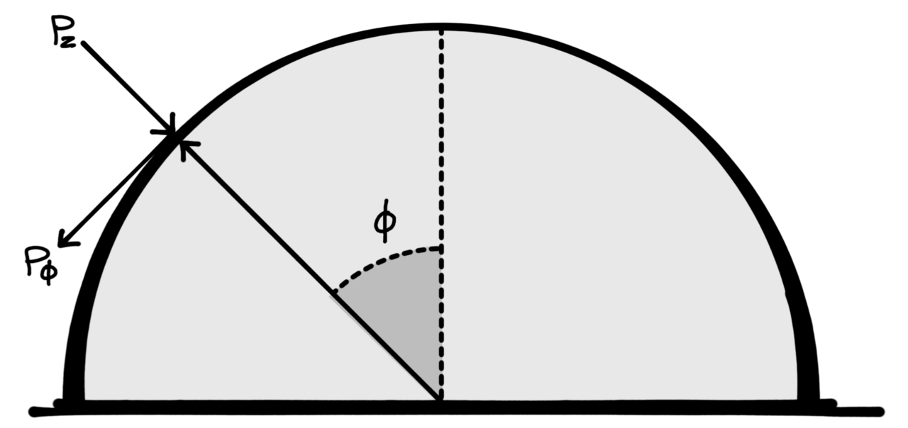
Figure 1. The elevation profile of wind forces affecting a concrete dome.
Concrete dome wind analysis
Example 1
Commercial dome building 30 feet high in exposure C — the most severe exposure in open, flat terrain. Using wind design pressure from UBC 1985 Edition, section 2311.d, of 70 MPH.
- p = Ce Cq Qs I
- I = 1.0 (commercial building)
- Qs = 13 psf (pressure from wind)
- Ce = 1.3 (building height 30-feet, exposure C)
- Cq = 1.3 (method 2)
Therefore, p = 1.3 × 1.3 × 1.3 psf × 1.0 = 22 psf
Example 2
Assume same building from Example 1 and same exposure but with a wind speed of 300 MPH. (Reference: Fine, Mark, Handbook of Concrete Engineering; Nan Nostrand Reinhold, 1974.)
- p = ½ Cs Ca Cg P Vh2 (H/h)2/φ
Assume everything is constant except the wind speed.
- P = C Vh2 = 22 psf for V = 70 MPH (example 1)
- Therefore, C = 22 / 702 = 0.00449
- Then, p = 0.00449 Vh2 for V = 300 MPH; p = 404 psf
The maximum concrete stress in a dome 100 feet in diameter by 30 feet high with p = 400 psf is 1,098 psi compression. From the “Concrete dome seismic analysis” example (below) we see the allowable stress is significantly higher at 2,394 psi.
The Monolithic Dome at Port Arthur, Texas, has now been hit by three hurricanes. A hurricane does not exert enough pressure on a dome to be even noticed. As shown above, the dome can very easily withstand the stresses of a tornado.
However, debris carried by a tornado could cut the surface membrane. If the debris contained a large timber or metal object, it might be possible if conditions were just right to put a puncture into the dome. But the puncture would be very local and would certainly never cause a serious collapse of the dome. Possibly damage to the doors or windows may occur if there was a rapid decompression caused by the tornado.

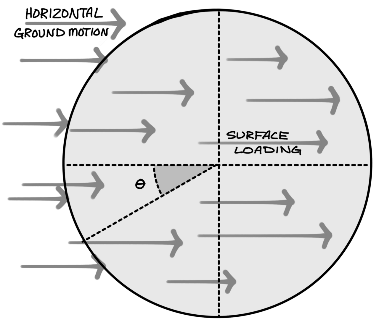
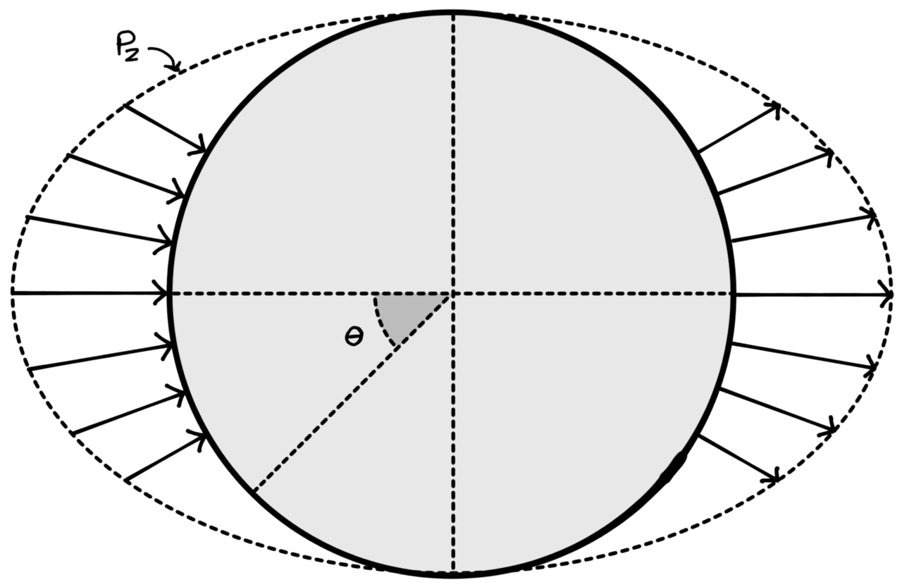
Figure 3. Reference drawing of relevant variables for seismic analysis.
Concrete dome seismic analysis
- Dome Diameter = 110’
- Dome Height = 37’
- Dome Thickness = 3" @ top and 8" @ bottom
Reference: Billington 1985 Ed., p. 55
- pz = p cos θ sin φ
- pφ = pθ = 0
Membrane Forces
- Nφ = −a p k1 cos θ
- Nφ θ = −a p k2 sin θ
- Nθ = −a p k3 cos θ
Seismic Force Reference: UBC 1985 Edition
- V = Z S I C K (Formula for the total design lateral force)
- Z = 1.0 Zone IV (seismic zone factor)
- C × S = 0.14
- I = 1.5 (Importance factor = hospital)
- K = 2.0 (Unusual building such as a dome — very conservative)
Analysis
- Therefore, V = 1.0 × 1.5 × 0.14 × 2.0 W = 0.420 W (Note, V = 0.14 W for normal shear wall building!)
- V = 0.420 × 100 = 42.0 psf (One square foot of shell 8” thick weighs 100 lbs.)
- The value of p = V = 42.0 psf.
- For demonstration purposes assume p = 60 psf. This represents earthquake forces in excess of the most severe code requirement by a factor of 1.4.
- Maximum stress due to Nθ is −64.8 psi; Nφ is −70.6 psi. Maximum bending moment is 909.3 lbs-ft/ft.
- For a vertical live load of 40 psf in addition to the dead load of the shell the following stresses and moment are obtained. Maximum stress due to Nφ = −82.5 psi; Nθ = −70.7 psi or 0.146.5 psi. The maximum bending moment is 1,588.0 lbs-ft/ft.
- The maximum allowable compressive force in the concrete is: fc = 1.33 × 0.45 × 4000 psi = −2.394 psi. This is many times greater than the −70.6 psi needed.
The forces caused by a major earthquake are considerably less than normal provided for when a dome is designed for nominal vertical loads.

Figure 4. Plan diagram of how horizontal forces from an earthquake are distributed across the surface of a concrete dome.
Earthquake resistance
For most Monolithic domes, the likely disaster will be an earthquake. The worst areas in the United States are listed as seismic zone 4. From our analysis above, it is easy to see that earthquake forces do not even approach the design strength the Monolithic Dome is built to withstand under normal everyday usage. It would take an external force many times as large as the earthquake to approach the design strength of the concrete itself.
Nuclear fallout
Nuclear fallout is another disaster consideration. It is interesting to note that the only structure left standing near ground zero at Hiroshima was the concrete skeleton of a dome. Certainly, the Monolithic Dome would be superior to most buildings if a nuclear fallout condition occurred. Rain would tend to wash the radiation off the building much better than conventional buildings.
Generally, the Monolithic Dome is quite tall. Radiation strengths are inversely proportional to the square of the distance from the source. The roof of the Monolithic Dome would hold the radiation further from the occupants than many other structures. Also concrete itself is a good absorber of radiation. The concrete Monolithic Dome would greatly reduce the effects of fallout on the occupants.
It is interesting to note that German thin shell structures stood up to allied bombing in the second world war better than most other structures. When a bomb would hit a thin shell it would either bounce off its tough resilient exterior or it would puncture a hole through.
Since there are no single components that carry large loads, there is nothing that can be knocked down like a beam or a column. Therefore repair was a simple patch to cover the hole that was made when the bomb would go through.
Conclusion
The forces caused by wind and earthquake on a concrete dome generally do not control the design. Domes are very strong and durable and in a realistic situation would probably still be standing when all conventional structures had failed.
In 1986, Arnold Wilson, Ph.D, S.E. wrote this seminal whitepaper analyzing the tornado and earthquake resistance of concrete thin-shells constructed using the Monolithic Dome construction method. This republication was drawn from various copies of his original work. We updated the drawings, fixed grammar mistakes, and carefully reviewed the mathematics.
At the time, Dr. Wilson was a professor of Civil Engineering at Brigham Young University and the structural engineer for many early Monolithic Dome structures. In the following decades, he taught with distinction at BYU, mentored many new engineers, and was the engineer of record for over a thousand concrete thin-shell and Monolithic Dome structures. He retired in 2010.
In 2005, Dr. Wilson literally wrote the book on the Monolithic Dome and concrete shells with his textbook, “Practical Design of Concrete Shells.”
