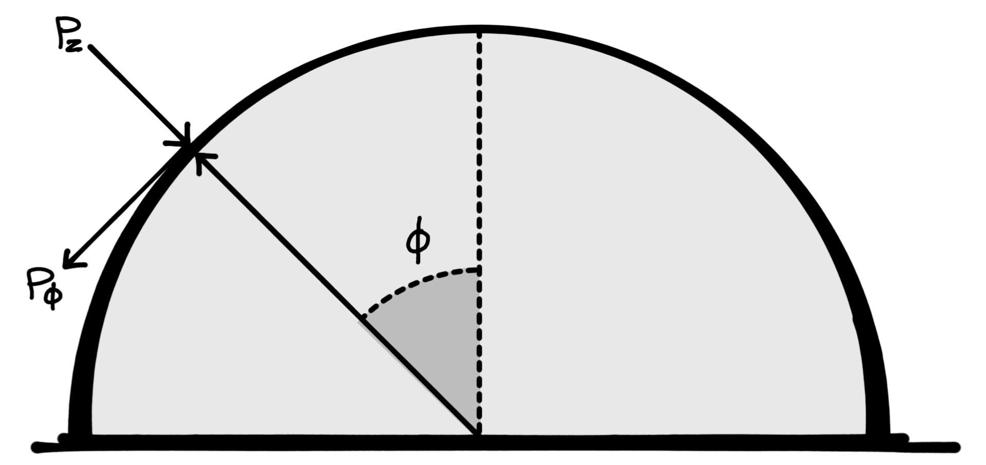
Elevation diagram referencing variables used it seismic analysis.
Figure 3. Reference drawing of relevant variables for seismic analysis.
Concrete dome seismic analysis
- Dome Diameter = 110’
- Dome Height = 37’
- Dome Thickness = 3" @ top and 8" @ bottom
Reference: Billington 1985 Ed., p. 55
- pz = p cos θ sin φ
- pφ = pθ = 0
Membrane Forces
- Nφ = −a p k1 cos θ
- Nφ θ = −a p k2 sin θ
- Nθ = −a p k3 cos θ
Seismic Force Reference: UBC 1985 Edition
- V = Z S I C K (Formula for the total design lateral force)
- Z = 1.0 Zone IV (seismic zone factor)
- C × S = 0.14
- I = 1.5 (Importance factor = hospital)
- K = 2.0 (Unusual building such as a dome — very conservative)
Analysis
- Therefore, V = 1.0 × 1.5 × 0.14 × 2.0 W = 0.420 W (Note, V = 0.14 W for normal shear wall building!)
- V = 0.420 × 100 = 42.0 psf (One square foot of shell 8” thick weighs 100 lbs.)
- The value of p = V = 42.0 psf.
- For demonstration purposes assume p = 60 psf. This represents earthquake forces in excess of the most severe code requirement by a factor of 1.4.
- Maximum stress due to Nθ is −64.8 psi; Nφ is −70.6 psi. Maximum bending moment is 909.3 lbs-ft/ft.
- For a vertical live load of 40 psf in addition to the dead load of the shell the following stresses and moment are obtained. Maximum stress due to Nφ = −82.5 psi; Nθ = −70.7 psi or 0.146.5 psi. The maximum bending moment is 1,588.0 lbs-ft/ft.
- The maximum allowable compressive force in the concrete is: fc = 1.33 × 0.45 × 4000 psi = −2.394 psi. This is many times greater than the −70.6 psi needed.
The forces caused by a major earthquake are considerably less than normal provided for when a dome is designed for nominal vertical loads.
Posted to Building Survivability: A Guru's Analysis of Monolithic Dome Tornado and Earthquake Resistance
© All Rights Reserved
